Impressive Tips About How To Calculate PWM Frequency

STM32 PWM Frequency & Resolution Configuration
Understanding PWM Frequency
1. What's the Buzz About PWM?
Ever wondered how that fancy LED dimmer works, or how your computer fan manages to spin at just the right speed? The secret often lies in Pulse Width Modulation, or PWM. Think of it as a super-fast on-off switch that controls the amount of power delivered to a device. Instead of a constant stream, it sends pulses, and the width of those pulses determines the average power. So, if the pulse is 'on' for a longer time, the device gets more power. But how do we figure out how fast this switch is flipping? That's where PWM frequency comes in!
Why is the frequency important, you ask? Well, imagine flickering lights. Annoying, right? A low PWM frequency can cause exactly that noticeable flickering, especially with LEDs. A higher frequency, on the other hand, makes the switching so fast that our eyes can't detect it, resulting in smooth, continuous operation. Also, in audio applications, a low PWM frequency can introduce unwanted noise. So, getting the frequency right is kinda crucial!
Before we dive into the calculations, let's get something straight. The term "PWM frequency" is a noun phrase; more specifically it's a noun phrase functioning as the subject of many sentences when discussing this topic. It defines how quickly those pulses are happening. Think of it like beats per minute in music — it sets the pace! Understanding this fundamental concept is key to getting the most out of PWM in your projects.
So, PWM frequency is not just some technical jargon; it's a vital parameter that affects performance and perceived quality of a wide range of devices and systems. Getting it right ensures smooth, efficient operation, and avoids annoying side effects like flickering or unwanted noise. Let's explore how to calculate it.

The Anatomy of a PWM Signal
2. Deconstructing the Pulse
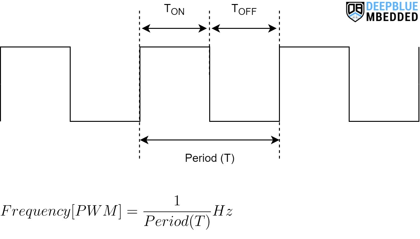
To calculate PWM frequency effectively, it's helpful to picture the waveform. Every PWM signal has two key parts: an 'on' time and an 'off' time. The 'on' time, often called the pulse width, is the duration for which the signal is high (usually at the maximum voltage, like 5V or 3.3V). The 'off' time is the duration for which the signal is low (usually 0V or ground). This cycle of 'on' and 'off' repeats continuously, creating a stream of pulses.
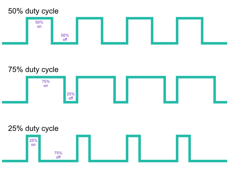
The duty cycle is another critical concept. It represents the percentage of time the signal is 'on' during one complete cycle. For example, a 50% duty cycle means the signal is 'on' for half the time and 'off' for the other half. A 10% duty cycle means it's 'on' for only 10% of the time, and so on. The duty cycle directly controls the average power delivered to the device. A higher duty cycle means more power, and a lower duty cycle means less power. Think of it as adjusting the volume knob on a radio — more 'on' time equals more volume (or power!).
The PWM frequency is essentially the number of these complete 'on-off' cycles that occur in one second. It's measured in Hertz (Hz), which means cycles per second. A frequency of 100 Hz means the signal completes 100 cycles every second. Knowing both the duty cycle and the frequency allows you to fully characterize a PWM signal and predict its behavior.
It's important to remember that the relationship between frequency and duty cycle is independent. You can have a high frequency signal with a low duty cycle, or a low frequency signal with a high duty cycle, or any combination in between. Understanding this independence is key to controlling your PWM output effectively. Visualize them as separate knobs you can adjust to fine-tune your system.

OnTime Cycle In Pulse Width Modulation (PWM) Arduino PWM Has 500Hz
The Formula for Calculating PWM Frequency
3. Putting Numbers to Pulses
Okay, let's get to the math! The formula for calculating PWM frequency is surprisingly simple: Frequency (Hz) = 1 / Period (seconds)
The period is the total time it takes for one complete cycle, from the start of the 'on' time to the end of the 'off' time. If you know the period of your PWM signal, calculating the frequency is a piece of cake. But what if you don't know the period directly?
Well, often, you might know the clock frequency of the microcontroller or timer generating the PWM signal, and the number of ticks per cycle. In that case, you can find the period. For example, imagine a microcontroller with an 8 MHz clock and a timer configured to count 8000 ticks per PWM cycle. The period will be 8000 / 8,000,000 = 0.001 seconds. The frequency then becomes 1 / 0.001 = 1000 Hz. Simple, right?
Its essential to use consistent units. If your period is in milliseconds (ms), convert it to seconds by dividing by 1000 before plugging it into the formula. Likewise, if your frequency is in kHz (kilohertz), multiply it by 1000 to convert it to Hz. Double-checking your units will save you from making silly mistakes and ending up with wildly incorrect results.

PWM Pulsewidth Modulation Soldered Electronics
Practical Examples
4. Let's Get Real
Let's say you're controlling the brightness of an LED using an Arduino. You've set up your PWM pin to have a period of 0.002 seconds. To find the frequency, you simply use the formula: Frequency = 1 / 0.002 = 500 Hz. This means the LED is being switched on and off 500 times per second.
Now, imagine you're working with a motor controller and want to adjust the speed of a DC motor. You measure the period of the PWM signal to be 0.0005 seconds. Applying the formula, you get: Frequency = 1 / 0.0005 = 2000 Hz. A frequency of 2 kHz might be suitable for many DC motors, but you should always check the motor's datasheet to ensure it's within the recommended range.
One more example: Suppose a microcontrollers PWM configuration specifies a clock frequency of 16 MHz and a prescaler of 64, and a timer count of 250. Here, the frequency will be Clock frequency / (Prescaler Timer count) = 16,000,000 / (64 250) = 1000 Hz. This example combines multiple concepts we've talked about so far.
Always remember to consider the limitations of your microcontroller or PWM controller. Some devices have a maximum PWM frequency that they can generate accurately. Exceeding this limit can lead to unexpected behavior or even damage to the device. Check your documentation to determine the safe operating range and choose your frequency accordingly.

Choosing the Right PWM Frequency
5. Frequency Fine-Tuning
Selecting the appropriate PWM frequency depends heavily on the application. For LEDs, you generally want a high enough frequency (above 200 Hz) to avoid visible flickering. But going too high might create other problems due to switching losses within the driving circuitry.
When controlling motors, the ideal frequency depends on the motor's characteristics. Lower frequencies can cause audible noise and jerky movement, especially at low speeds. Higher frequencies can reduce the torque the motor can generate. Again, consulting the motor's datasheet is critical.
In audio applications, PWM is often used for Class-D amplifiers. Here, the PWM frequency needs to be significantly higher than the highest audio frequency you want to reproduce (typically above 20 kHz). This ensures that the switching noise is outside the audible range.
Ultimately, there's often a trade-off between performance, efficiency, and noise. Experimentation and careful consideration of your specific requirements are essential for choosing the optimal PWM frequency. Don't be afraid to try different frequencies and observe the results. This is where the fun begins!
Digital IVision Labs! PWM In Arduino
FAQ
6. Your PWM Questions Answered
7. Q
A: A low PWM frequency can cause noticeable flickering in LEDs, audible noise in motors, and distortion in audio amplifiers. It's generally best to choose a frequency high enough to avoid these issues, but low enough to prevent excessive switching losses.
8. Q
A: The duty cycle doesn't directly affect the PWM frequency. The frequency is determined by the period of the PWM signal, while the duty cycle determines the proportion of time the signal is 'on' during each cycle. They're independent parameters.
9. Q
A: Yes, you can change the PWM frequency on an Arduino, but it requires modifying the timer settings directly. Be cautious when doing this, as incorrect settings can disrupt other Arduino functions that rely on the same timers. There are libraries and tutorials available online to guide you through this process safely.