Underrated Ideas Of Info About What Is A 3 Phase Rectifier Circuit

Delving into the World of 3-Phase Rectifier Circuits
1. What's the Big Deal with Three Phases Anyway?
Alright, let's talk about converting AC (alternating current) to DC (direct current). It's a pretty common thing, right? Your phone charger does it, your laptop adapter does it, and all sorts of other electronic gadgets rely on this conversion process. But sometimes, you need a lot of DC power, and that's where things get interesting — that's where the 3-phase rectifier circuit comes into play.
Think of regular single-phase AC like a bicycle with one pedal. It goes up and down, delivering power in pulses. A 3-phase system, on the other hand, is like a bicycle with three pedals spaced evenly apart. This gives you a much smoother and consistent power delivery. It's less bumpy and more efficient, especially when dealing with heavy loads like motors or industrial equipment. Imagine trying to power a factory with just a single-phase outlet — it wouldn't be pretty!
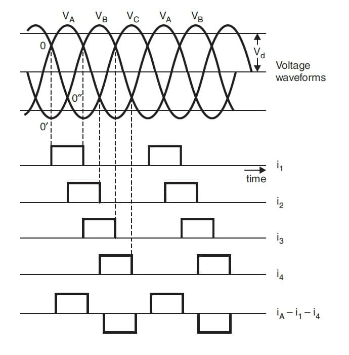
So, why three phases instead of just one? Well, the primary reason is that three-phase power provides a more consistent and higher power output compared to single-phase. The overlap of the three phases means that power is almost always being delivered, leading to a smoother DC output after rectification. This also reduces the size and cost of filtering components needed to smooth out the DC voltage, saving you money in the long run. And who doesn't like saving money?
Using a 3-phase rectifier circuit is also advantageous because it allows you to use smaller and lighter transformers and conductors compared to a single-phase system that delivers the same power. The more phases, the better the power distribution and all the equipment related to it will be less bulky and costly. That's why you'll find three-phase power used in industries, large commercial buildings, and even some homes that require high power consumption. Let's just say it's the superhero of power distribution!

Three Phase Full Wave Bridge Rectifier Circuit Diagram Singl
Breaking Down the 3-Phase Rectifier Circuit
2. Diodes
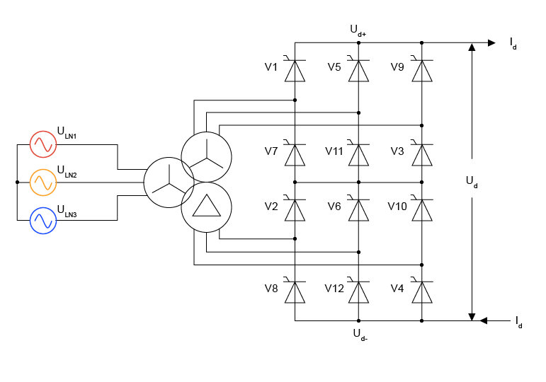
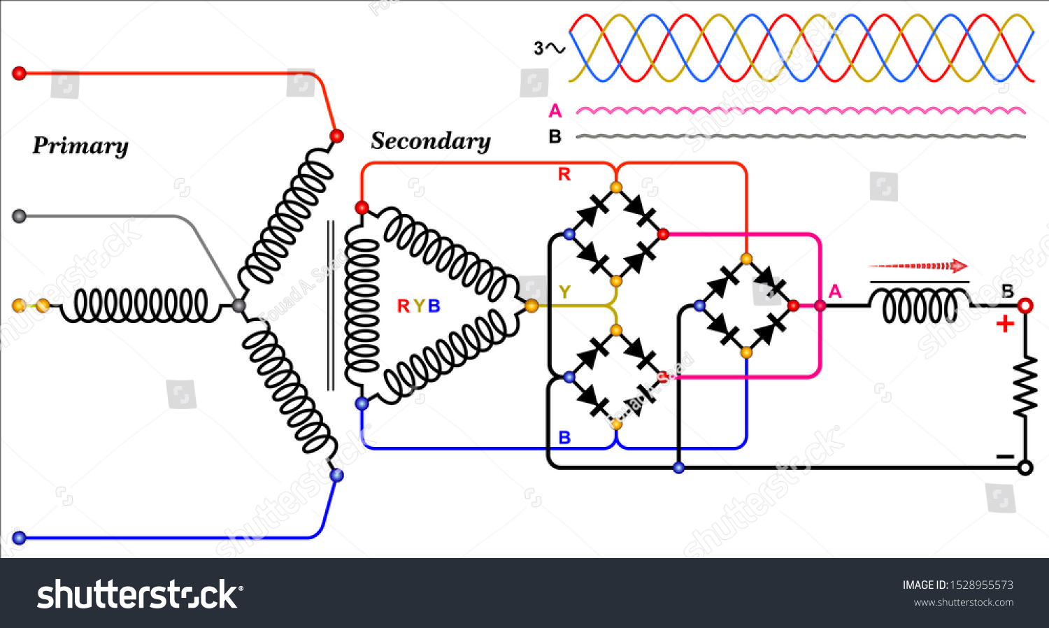
Now, let's dive a little deeper into the circuit itself. The heart of a 3-phase rectifier is a bunch of diodes — typically six of them in a standard configuration. Diodes are like one-way streets for electricity. They only allow current to flow in one direction, which is essential for converting AC to DC. They're simple components, but they perform a critical function in this circuit.
These diodes are arranged in a specific way, usually in a bridge configuration, to ensure that the AC voltage is converted into DC. Imagine each diode as a gatekeeper, only opening when the voltage is positive and blocking it when it's negative. This clever arrangement allows the circuit to take the positive portions of the AC waveform and direct them to the DC output, creating a pulsating DC voltage. It's like a synchronized dance of electrons!
There are two main types of 3-phase rectifier circuits: the half-wave rectifier and the full-wave rectifier. The half-wave rectifier is simpler, using fewer diodes, but it's also less efficient. The full-wave rectifier, which is more common, uses more diodes but provides a smoother and more efficient DC output. Think of it like choosing between a basic bicycle and a high-performance road bike; both will get you there, but one will do it faster and more efficiently. Most of the time, you want the full-wave version because you want to harness more power, right?
The selection of the specific diode is crucial to the proper operation of a 3-phase rectifier circuit. These selections should be based on their peak inverse voltage (PIV) and forward current (IF) capacity. It's important to consider both the maximum voltage that the diode will be subjected to when it is reverse-biased (PIV) and the maximum current that the diode will conduct when it is forward-biased (IF). Selecting diodes with adequate ratings ensures reliable and efficient performance of the circuit. Not all diodes are created equal, and the right choice can make all the difference in the long run.

Smoothing Things Out
3. Capacitors
So, we've converted AC to a pulsating DC voltage, but it's not quite smooth enough for most applications. That's where filtering comes in. A filter, typically consisting of capacitors and sometimes inductors, is used to smooth out the DC voltage and reduce the ripple. Capacitors are like small rechargeable batteries; they store energy and release it when needed. And the ripple that needs to be reduced is the small, unwanted variations or fluctuations in the DC voltage. It's like trying to watch a movie on a screen that's flickering slightly.
The capacitor charges up during the peaks of the pulsating DC voltage and discharges during the valleys, effectively filling in the gaps and creating a smoother DC output. Think of it like a water reservoir that stores water during periods of high rainfall and releases it during dry spells. This process is repeated for each voltage spike. The larger the capacitor, the better it can smooth out the DC voltage, but bigger isn't always better; there are trade-offs to consider, such as cost and size. In the end, this process ensures a stable DC supply for whatever device or application is receiving power.
Inductors, while less commonly used in simpler rectifier circuits, can also be part of the filtering process. They resist changes in current, helping to further smooth out the DC output. The combination of capacitors and inductors creates a more robust filter, capable of handling more demanding applications. These inductors smooth current and capacitors will smooth voltage. Both are desirable for a more precise voltage and more consistent electricity throughput.
Without proper filtering, the ripple in the DC voltage can cause problems with sensitive electronic equipment. It can lead to erratic behavior, reduced performance, and even damage. That's why filtering is such an important step in the rectifier circuit. Imagine trying to run a delicate computer system on a power supply that's constantly fluctuating — it wouldn't last long! So, the better the filtering, the happier your electronics will be.

Rectifier Circuit With Battery Input
Applications Galore
4. From Industrial Power to Electric Vehicles
Now that we know how 3-phase rectifiers work, let's talk about where they're used. These circuits are essential in a wide range of applications where high DC power is required. One of the most common applications is in industrial power supplies. Factories, manufacturing plants, and other industrial facilities often rely on 3-phase power to run heavy machinery, and 3-phase rectifiers are used to convert the AC power to DC power for various equipment.
Another important application is in variable frequency drives (VFDs). VFDs are used to control the speed of AC motors, and they require a DC power supply. A 3-phase rectifier is used to convert the incoming AC power to DC power, which is then used to drive the motor. This allows for precise control of the motor speed, which is essential in many industrial processes. It's like having a gas pedal for your electric motor!
Electric vehicles (EVs) are another growing application for 3-phase rectifiers. EVs use batteries as their primary power source, and these batteries need to be charged. A 3-phase rectifier is used to convert the AC power from the grid to DC power to charge the battery. As EVs become more popular, the demand for efficient and reliable 3-phase rectifiers will continue to grow. Plus, the charging stations themselves utilize these rectifier circuits.
Beyond these common examples, 3-phase rectifiers are also used in applications like uninterruptible power supplies (UPS), welding equipment, and even some high-power audio amplifiers. Basically, any application that needs a lot of DC power is likely to use a 3-phase rectifier. So, the next time you see a large piece of equipment humming away, chances are there's a 3-phase rectifier working hard inside.

Full Wave Rectifier Circuit Diagram Class 12
Advantages and Disadvantages
5. Everything has Pros and Cons, Right?
Like any technology, 3-phase rectifier circuits have their advantages and disadvantages. One of the biggest advantages is their efficiency. They provide a smoother and more consistent DC output compared to single-phase rectifiers, leading to less energy waste. Also, as mentioned earlier, the fact that three-phase power distributes more evenly and consistently across the application is advantageous. This ensures less down-time, more consistent output, and reduced energy consumption. All of these are good for both the operation and the budget.
Another advantage is their ability to handle high power levels. They can easily handle the high power demands of industrial equipment, electric vehicles, and other heavy-duty applications. Because of this, the 3-phase rectifier circuits can provide a more reliable power conversion system in these industries and heavy-duty applications. With proper care and maintenance, they can provide years of quality power conversion service.
However, 3-phase rectifier circuits can be more complex and expensive than single-phase rectifiers. They require more components, such as diodes and filtering components, which can add to the cost. A proper selection of components can actually help reduce costs. However, it is more likely to require a skilled technician who understands all the requirements to operate. If that is not possible, it is more likely that costs will be higher. So, the extra care and attention is required for this system.
Also, they require a three-phase AC power source, which may not be available in all locations. In residential areas, single-phase power is more common, which means that a 3-phase rectifier cannot be used directly. So, depending on how and where you use it, it could require more complex electrical equipment for operation. Even so, when the need arises for more power, it's hard to beat a 3-phase system. The best of all worlds is to have the system operate near maximum efficiency.

FAQ
6. Your Burning Questions Answered!
Still scratching your head about 3-phase rectifiers? No worries! Here are some frequently asked questions to clear up any lingering confusion:
Q: Why are six diodes typically used in a 3-phase full-wave rectifier?
A: Six diodes are used to ensure that all three phases of the AC input are rectified, providing a full-wave rectified DC output. This configuration maximizes efficiency and minimizes ripple in the DC voltage.
Q: What happens if one of the diodes in a 3-phase rectifier fails?
A: If a diode fails, the rectifier's performance will be affected. The output voltage will likely decrease, and the ripple will increase. In some cases, the rectifier may stop working altogether. It's like a flat tire on your car — you can't go very far!
Q: Can I use a 3-phase rectifier to power a single-phase device?
A: Yes, but you'll need to use a DC-to-AC inverter to convert the DC output of the rectifier back to single-phase AC power. It's like translating from one language to another — you need a translator to bridge the gap!