Beautiful Work Tips About Which GPIO Pins Are PWM

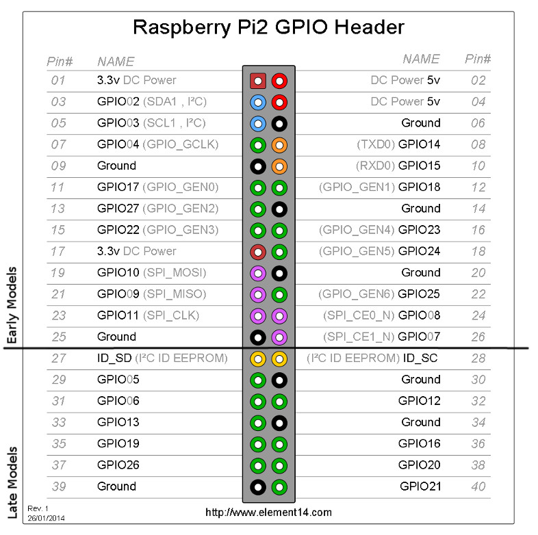
MENGENAL SINGLE BOARD KOMPUTER RASPBERRY Pi 3 MODEL B+ LAB ELEKTRONIKA
Decoding PWM on GPIO Pins
1. What's the Big Deal About PWM, Anyway?
Okay, so you're tinkering with microcontrollers and you keep hearing about PWM. What's the hype? Well, PWM, or Pulse Width Modulation, is a clever technique that lets us simulate analog signals using digital outputs. Think of it like this: instead of a dimmer switch that smoothly changes brightness, PWM rapidly switches a light on and off. By varying how long the light is "on" versus "off" (the pulse width), we can control the perceived brightness. This is incredibly useful for controlling things like motor speed, LED brightness, and even servo motor position.
Why is this so important? Because many microcontrollers only have digital output pins — they're either on or off. PWM gives us a way to get "in-between" states without needing actual analog outputs, which are often more complex and expensive to implement. It's like magic, but with electrons.
Consider a scenario: you want to dim an LED using your microcontroller. You could use a resistor to limit the current, but that's inefficient and doesn't give you fine-grained control. With PWM, you can adjust the brightness in small increments, making your LED glow just the way you want it. Plus, you can create cool fading effects! Think of the possibilities!
Essentially, PWM is the Swiss Army knife of digital control. It's versatile, efficient, and opens up a whole new world of possibilities for your electronic projects. It's one of those fundamental concepts that every maker should understand.
2. Pinpointing PWM-Capable GPIOs
Alright, so you're convinced PWM is awesome. But how do you actually use it? The key is figuring out which of your microcontroller's GPIO (General Purpose Input/Output) pins are capable of PWM. Not all pins are created equal, sadly. Some are just plain digital I/O, while others have the special hardware needed for PWM generation.
The easiest way to find out which pins support PWM is to consult the datasheet or the documentation for your specific microcontroller. Look for phrases like "PWM output," "timer/counter output," or "compare output." These usually indicate that the pin is connected to a PWM-capable timer module inside the chip.
Don't be intimidated by the datasheet! It might look like a wall of text, but the pinout diagram is your friend. It'll usually show which pins have PWM capabilities labeled directly on the diagram. Websites dedicated to your specific board will also usually have very easy to understand pinouts. For example, if you are working with a Raspberry Pi Pico, searching "Raspberry Pi Pico pinout PWM" will quickly lead you to the answer.
It's important to note that the number of PWM-capable pins varies greatly depending on the microcontroller. Some chips might have only a couple, while others have a dozen or more. Choose your microcontroller wisely based on the number of PWM outputs you think you'll need for your project. Also, sometimes you can reconfigure pins with alternate functions to enable PWM, but that gets more complex!
Examples of PWM Pins in Popular Microcontrollers
3. Arduino Uno
The Arduino Uno is a classic for a reason. It's easy to use and widely supported. On the Uno, the PWM-capable pins are marked with a tilde (~) symbol on the board. These are pins 3, 5, 6, 9, 10, and 11. These pins are connected to the built-in timers of the ATmega328P microcontroller, which allows them to generate PWM signals.
Using these pins is pretty straightforward. In the Arduino IDE, you use the `analogWrite()` function to set the PWM duty cycle. The duty cycle is a value between 0 and 255, representing the percentage of time the pin is "on" during each PWM cycle. For example, `analogWrite(9, 128)` would set pin 9 to a 50% duty cycle.
One quirk to remember: the Arduino Uno's PWM frequency is around 490 Hz for most pins, but pins 5 and 6 operate at about 980 Hz. This difference can sometimes affect the behavior of certain devices, so keep it in mind when designing your project.
The Arduino Uno is a fantastic option for learning the basics of PWM. The simple syntax and wealth of online resources make it easy to get started and experiment with different PWM applications.
4. Raspberry Pi Pico
The Raspberry Pi Pico is a powerful little board based on the RP2040 microcontroller. It offers a lot of flexibility when it comes to PWM. Almost any GPIO pin on the Pico can be configured for PWM, thanks to its Programmable Input/Output (PIO) state machines. This makes it incredibly versatile for a wide range of projects.
While technically most GPIO pins can be used for PWM, understanding how the Pico's PWM system works is crucial. The PWM 'slices' have two channels (A and B), so it's more about assigning a pin to a slice/channel combo. MicroPython libraries like `machine.PWM` make using PWM relatively easy, but you'll need to specify which pin is connected to which PWM channel.
The flexibility of the Pico comes at the cost of some added complexity. You'll need to understand how to configure the PIO state machines or use the provided libraries to set up PWM on the desired pins. However, once you get the hang of it, you can create some very sophisticated PWM control systems.
The Pico is a fantastic choice for more advanced projects that require fine-grained PWM control or a large number of PWM outputs. Its powerful processor and flexible architecture make it a great platform for experimenting with PWM in various applications.
5. ESP32
The ESP32 is known for its Wi-Fi and Bluetooth capabilities, but it's also a very capable microcontroller with plenty of PWM pins. The ESP32 has 16 independent PWM channels that can be assigned to any of its GPIO pins (with a few exceptions, of course — always check the datasheet!).
Using PWM on the ESP32 involves configuring the PWM channels and then assigning them to specific GPIO pins. You can set the PWM frequency and duty cycle independently for each channel, giving you a lot of control over your outputs. The ESP32 also supports features like fade in/out effects and variable frequency PWM.
The ESP32's PWM capabilities are impressive. It supports a wide range of frequencies and duty cycles, making it suitable for demanding applications like motor control and LED lighting. Plus, the ESP32's built-in Wi-Fi and Bluetooth connectivity open up even more possibilities for remote control and monitoring of your PWM-controlled devices.
If you're looking for a microcontroller with a good balance of PWM capabilities, connectivity, and processing power, the ESP32 is definitely worth considering. It's a popular choice for IoT projects and other applications that require wireless communication and sophisticated control.

Arduino Nano Which Pins Are Pwm
Understanding Duty Cycle and Frequency
6. Duty Cycle
The duty cycle is the heart of PWM. It represents the percentage of time that the PWM signal is high (on) during each cycle. It's usually expressed as a percentage, ranging from 0% to 100%. A 0% duty cycle means the signal is always low (off), while a 100% duty cycle means the signal is always high (on). A 50% duty cycle means the signal is high for half the time and low for the other half.
Adjusting the duty cycle is how we control the average voltage (or current) delivered to a device. For example, if you're using PWM to control an LED, a higher duty cycle will make the LED brighter, while a lower duty cycle will make it dimmer. Similarly, with a motor, a higher duty cycle will make it spin faster.
Think of it like a water faucet. The duty cycle is like how long you open the faucet each second. A short burst (low duty cycle) gives you a trickle of water, while keeping it open longer (high duty cycle) gives you a strong flow. PWM does the same thing with electricity, but much, much faster!
Most microcontrollers provide functions to easily set the duty cycle as a percentage or a value within a specific range (e.g., 0-255 or 0-1023). Understanding how the duty cycle affects your output is crucial for achieving the desired results in your projects.
7. Frequency
The frequency of a PWM signal determines how often the cycle repeats per second. It's measured in Hertz (Hz), which represents cycles per second. A higher frequency means the signal switches on and off more rapidly, while a lower frequency means it switches more slowly.
The choice of PWM frequency depends on the application. For controlling LEDs, a frequency of a few hundred Hz is usually sufficient. However, for controlling motors, a higher frequency might be needed to avoid audible noise or jerky movements. The human ear can detect frequencies up to about 20 kHz, so a PWM frequency above that is generally considered "silent."
A lower PWM frequency can sometimes lead to flickering in LEDs or audible hum in motors. A higher PWM frequency can reduce these effects, but it also increases the processing load on the microcontroller. It's all about finding the right balance.
Some microcontrollers allow you to adjust the PWM frequency, while others have a fixed frequency. If you have the option, experiment with different frequencies to see how they affect your application. Remember, the "best" frequency depends on the specific device you're controlling and the desired performance.
Practical Applications of PWM
8. Dimming LEDs
One of the most common uses of PWM is controlling the brightness of LEDs. By varying the duty cycle, you can smoothly adjust the brightness from a subtle glow to full brightness. This is perfect for creating mood lighting, indicator lights, or even complex lighting effects.
Think about a smart home lighting system. You could use PWM to dim the lights automatically based on the time of day or to create different lighting scenes for different activities. You could even use PWM to create a simulated sunrise effect, gradually increasing the brightness of the lights in the morning.
PWM is also used in LED displays to control the brightness of individual pixels. This allows for a wide range of colors and shades to be displayed. Whether it's a simple seven-segment display or a large LED matrix, PWM is the key to controlling the brightness of the LEDs.
Beyond simple dimming, PWM can be used to create complex lighting effects like fading, strobing, and color mixing. With a little programming creativity, you can create some truly stunning visual displays using PWM and LEDs.
9. Controlling Motors
PWM is also essential for controlling the speed and direction of motors. By varying the duty cycle, you can adjust the voltage applied to the motor, which in turn controls its speed. This is used in everything from electric vehicles to robotics to household appliances.
In many robotics applications, PWM is used to control the speed and position of servo motors. Servo motors are used for precise movements, such as controlling the joints of a robotic arm or steering a remote-controlled car. PWM provides the fine-grained control needed for these applications.
For DC motors, you can use an H-bridge circuit in conjunction with PWM to control both the speed and direction of the motor. By switching the polarity of the voltage applied to the motor, you can make it spin in either direction.
From controlling the speed of a ceiling fan to precisely positioning a robotic arm, PWM is the workhorse behind many motor control applications. Its ability to provide smooth and efficient control makes it an indispensable tool for engineers and hobbyists alike.
10. Generating Audio Signals
While not as common as LED and motor control, PWM can also be used to generate audio signals. By rapidly switching a digital output on and off, you can create a square wave that approximates an audio waveform. By varying the duty cycle and frequency, you can control the pitch and volume of the sound.
This technique is often used in simple buzzers and speakers to generate beeps and tones. While the sound quality isn't as good as a dedicated audio amplifier, it's a simple and cost-effective way to generate basic audio signals.
More advanced techniques, like delta-sigma modulation, can be used to improve the audio quality of PWM-generated sounds. These techniques involve rapidly switching the PWM signal between different levels to create a more complex waveform.
Although PWM isn't the ideal choice for high-fidelity audio, it can be a useful tool for generating basic sounds in embedded systems. From simple alert tones to synthesized melodies, PWM can add an extra dimension to your projects.
FAQ
11. Q
A: Unfortunately, no. Only specific GPIO pins that are connected to the microcontroller's PWM controller can generate PWM signals. Consult your microcontroller's datasheet or pinout diagram to identify the PWM-capable pins. However, some advanced microcontrollers like the Raspberry Pi Pico allow you to configure almost any pin for PWM using clever programming.
12. Q
A: If you try to use PWM on a pin that doesn't support it, the pin will likely just behave as a regular digital output. It will either be on or off, without the ability to vary the pulse width. You won't damage anything, but you won't get the desired PWM effect. You might even get some very strange behaviour depending on how you try to output the PWM signal.
13. Q
A: Not necessarily. A higher PWM frequency can reduce flickering in LEDs and audible noise in motors, but it also increases the processing load on the microcontroller. In most cases, a frequency of a few hundred Hz to a few kHz is sufficient. Experiment to find the sweet spot for your application.
14. Q
A: The best PWM frequency depends on what you're controlling. For LEDs, anything above a few hundred Hz usually eliminates visible flicker. For motors, you might need a higher frequency to avoid audible noise. If you're using PWM to generate audio, you'll need a frequency that's within the audible range (20 Hz to 20 kHz). A good starting point is 1 kHz, and then you can adjust from there based on your observations.
